By this point the boys and I are getting anxious to get a test drive in, but we really need some brakes on our kart. I started this phase by first confirming exactly where to mount the crank in the frame. The challenge here is that I need to account for both 6 year olds and an 8 year old, so the length of their legs is quite different. If I placed the crank too far back my older son would hit his knees on the dash, but if I placed it too far forward my younger boys wouldn’t be able to reach it.
I had my oldest son sit in the kart and I immediately realized that, unfortunately, wherever I placed the crank he was going have trouble- you see his knees clearly were going to hit the dash. It was obviously just as much of an issue as to where the dash was placed as it was where the crank was placed. Unfortunately I already mounted the dash. Sigh. Well, I decided to remove the dash and rebuild it. Better to deal with this now rather than later.
I told my wife about this minor setback. She said that the only one that will be able to fit in the kart would be George, our medium sized mix breed Pinscher. I think she was joking because there is no way his rear paws could reach the pedals, his curly tail wouldn’t fit in the seat and I don’t think he could steer or at least not very well seeing that he has no opposable thumbs, besides that I think he has ADD so there is no way he would sit still long enough.
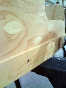
Anyway, I went and picked up another piece of 1×6 pine and penciled out a new dash. This time I took a slightly different approach in that I decided to make it taller (to account for space for their knees) and to also mount it higher in the body as well as a bit further forward. This higher placement would not just help with space, but also make the overall kart taller which will just look better as well. After cutting out the new dash I marked the place the steering column will come through. Like with my first pass at this step I will drill a 1″ hole through the dash for the steering column. The difference with this time is that I opted not to drill the hole square, but rather to drill it at about a 18 degree angle which will lean the steering wheel also a bit higher which will help with leg room.
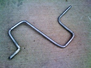
Next I determined where the crank would be placed in the frame and I drilled a pilot hole through the frame on both sides. Now on to manufacturing the crank itself. I headed back to Home Depot and picked up one 36″ length of 1″ non-threaded steel rod. Why non threaded you may ask? I’ll get to that in moment. Here I spent some time measuring, thinking, sketching, and doing more measuring before I proceeded. As the old saying goes, “Measure twice, bend once.“.
The objective here was to bend this rod into a crank, with each section being a specific length. At first glance it may not seem like much but I also had to account for the narrowing of the frame as the rider would turn the crank through it’s full rotation. On the forward part of a rotation the frame would be almost two inches narrower than when the rider had the other foot on the back side of the rotation.
I referred to our sacrificial Spiderman bike to determine how far the reach for each pedal should be. Knowing that I only had a total length of 36″ I didn’t have much room for error here. The bicycle had 6″ of reach for each pedal, that would mean that my crank would need 24″ just for the total of the pedal lengths, plus 4” for the “pedals” themselves. Throw in needed length on the ends and I realized that I needed to reclaim some otherwise my single 36″ piece just wasn’t going to work. I decided to make the throw, or length, of each pedal only 5″ instead of 6″. Doing this gives a bit more length that I could use on the sprocket side since it needs to reach out a few inches to align with the rear sprocket on our drive wheel, as well as makes it a bit easier to pedal for the little riders.
I measured out the segments on the rod and marked them with a permanent marker. I placed the rod in my bench vise and slipped a 4′ length of 3/4″ pipe over it. The boys were watching over my shoulder and Nick asked what I was going to do. I said “I’m going to bend this steel rod“. The word from his mouth simply was “Oh.“, but the look on his face said “Your yanking my chain Dad.“. I said here watch… and I proceeded to pull down on the pipe bending the first segment of 5” to 90 degrees (or thereabouts). The expression on his face was priceless. His mouth dropped open and his eyes were huge. I think from this day forward his Dad is, and always will be, the strongest man in the world.
I continued bending, measuring, and bending some more until I had something that resembled a starter handle from an old Model T Ford. One thing that I hadn’t even considered was if the pedals would sit too low to the ground!!?? Luckily that wasn’t the case. I wanted to put the crank in the frame next to get an idea of how well it would spin, etc. I slid in one side only to discover it was a hair too wide to allow me to insert the other side. I wasn’t suppose to assemble the frame around it… was I? Uggh. OK with a little elbow grease, and a big hammer, I was finally able to get it in.
At this point you can probably see why I opted not for threaded rod. I wanted to keep the pedals smooth allowing for their feet to slide easily as it turned, and only have threads on the outside to attach it within the frame. Now that the bends are complete I can use a die and thread both ends of the rod.
Now for another tricky step in this crank assembly…the sprocket. Remember, we took the sprocket from our Spiderman bike and we’re going to use that here. In some cases the donor bike may not be able to have the sprocket removed from the crank, so your mileage may vary.
Our goal here is to mount the sprocket on the left side in alignment to the sprocket on the left rear wheel. There are so many variable angles here working against me that makes this a really tough step. We have the narrowing frame, the rear wheels mounted outward to compensate, the hand bent crank, and the holes in the frame the crank sit in, not to mention the alignment of the Moon and planets. Each of these can contribute one way or another to what will likely be a somewhat wobbly chain. I figured I had a better chance of proposing a successful public health care reform bill than getting this all in perfect alignment, but I’ll take what I can get.
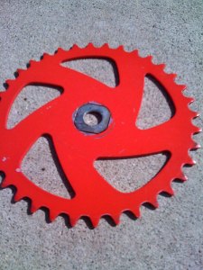
So focusing back on the sprocket itself. The sprocket has a hole in the center that is approximately 3/4″ in diameter. It’s not simply a perfect circle, but rather has squared corners that provided a tight fit onto the crank of the bicycle. That was all fine and good for Spiderman and his BMX crime fighting escapades, but what good does that do our go kart? I needed to figure out a way to reduce the size of that hole so that we can mount the sprocket onto our crank and secure it. After a visit to my local hardware store (sorry when it comes to unique washers and fittings Home Depot just doesn’t cut it) I found what looks to be an ideal solution. I’ll have to attack it in a few steps but I think it will work out just fine.
First step was to reduce the hole so that it will fit snugly. I found a 1/2″ washer that was just slightly larger than the hole in the sprocket. That is the center of the washer fit perfect over our crank, but the outside diameter was larger. I placed this washer underneath the sprocket on a flat surface and using a permanent marker I traced the shape of the hole in our sprocket onto the washer. This essentially made a template for me. I then grabbed some safety glasses, fired up my bench grinder and went to work.
From a distance the boys were watching me. As sparks bounced all over my hands and arms I could hear the boys yelling “Whoa!!!” and “Did you see those sparks!!!” followed with “That was awesome!!“. Not only am I the strongest man in the world but I can also deflect showers of sparks with my bare hands. I’m invincible! Well, at least to the boys I am, and that’s what really matters.
The sparks didn’t hurt much, but my wrist was a bit sore from bending the crank. If I’ve done anything with this project it’s show them just how willing I am to injure myself in the name of a go kart. Viva La Go Kart! I say.
In pretty short order I had a custom washer that fit just perfect. Next I whipped up a fresh batch of JB Weld. The ideal solution here would probably be to place a light mig weld to attach this washer to the sprocket, but since a mig welder is one tool I don’t have that’s far easier said than done. But what is JB Weld then you ask? It’s magic. Sort of. It’s a handy chemical compound (two compounds really) that when mixed together forms a bond between two pieces of steel that (in theory) is equivalent to a weld. I wouldn’t go quite that far, though I did have a friend in high school who repaired the intake manifold of a 1969 Camaro with it so it’s gotta be good enough for the go kart right?
I mixed equal parts of the JB Weld compound together and applied it to the edges where our new washer and the sprocket met. I then applied some more to two additional washers that I then placed on both sides, essentially sandwiching our custom washer in the middle.
Next I used a little more JB Weld to attach a castle nut onto our now custom sprocket. This nut will allow me to thread the entire sprocket onto the crank as a single unit. I waited a long 15 hours or so and carefully attached the sprocket assembly. The excitement was killing me. As it turned out the JB Weld just didn’t cut it when it came to ataching the chain. More on that below.
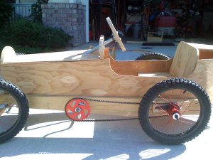
Now that we had the sprocket and the bent crank back in the frame I attached the sprocket onto the left side. I had the right idea with using JBWeld but unfortunately it just didn’t hold up once I attached the chain.
The force when the sprocket turned just was a bit too much. As soon as I put any kind of pressure here the castle nut would break away from the sprocket, and the sprocket would spin freely. As a result I just put a castle nut on both sides of the sprocket and cranked ‘er down with all I had. I was a bit worried I would strip the threads on the crank, but it seemed to hold.
Next I attacked the chain portion of this task. I took the chain from each donor bike, split them apart, and assembled one long chain to reach the back wheel. After I spent some time looking for a master link (that would have just been too simple now wouldn’t it have?) I just picked a random spot and wedged the link apart with a chisel. I reattached the ends of the chain together and voila… had a custom length chain to made order.
As they say, the devil is in the details, and these details are no different. I attached the chain and turned our pedals with the kart on the stand. I have to admit, seeing that wheel turn for the first time as a result of the hand bent crank, custom sprocket, etc. was pretty gratifying, but I have to say that the sprocket was wobbling all over the place. It was clear to me to that the chain would never stay on with that much travel.
It wasn’t the sprocket per se, but rather the bend of the crank. I removed the sprocket, removed the crank, and went back to the workbench for some more bending. I did this two or three times until I got the sprocket as close to “true” as I could. I still had a slight wobble, but not too bad, or so I thought.
Once I put the crank back into the frame, and was happy enough with the travel, I then adjusted the rear wheel to get the chain as tight as I could. I knew very well that anything I did at this point wasn’t absolutely final, but still wanted to get it as tight (not to mention safe) as I could since I wanted the boys to try it out. Finally I got it to the point where I asked if they could take ‘er for a spin down the street.

What good is a test vehicle without test drivers? Helmet and of course flip flops as any race driver can tell you are mandatory attire.
I’m not sure quite what I was expecting, but I know the boys and I were thrilled to see it reaching this point. I had people driving by stopping to check it out and a couple of people ask me if I sold them… “Let me get this one done first and I’ll get back to you” I said.
Off they went. As I feared, the boys were able to pedal for about 15 feet when our chain would derail. The crank was still a bit too wobbly. This combined with the effort I put in to readjust the dash and pedal length, to see it’s just still too unwieldy for my oldest son made me a bit cranky. I do think that if he could simply ride with his legs in front of him straight (as if pushing a gas/brake pedal) it would be just fine.
I’m afraid my wife was right that it was still too small, though I still don’t think George could drive it.
Although getting beyond my last update has taken 4+ weeks and I didn’t quite end up where I wanted to, I did make some good progress. I’ve realized that I don’t think I’m going to proceed with pedals but rather go straight to a motor of some sort. That makes this somewhat of a frustrating step, but not a complete loss. I haven’t done anything to this point I can’t back out of, so a motor (even a small one) will be where I’m headed. Eliminating pedals will save quite a headache not to mention make dealing with alignment of the rear wheel a bit easier.
I think I’ll try hitting the flea market and garage sales to find a used electric scooter. A gas motor sounds great and all, but I think the uniqueness of having this electric would just make it… well more unique. Although I was anticipating jumping into finishing work and getting our aluminum flashing in place by now, I’m hesitant to go too far since I’ll need to drill some access holes into the boat tail for a motor.
I’m hoping to get something soon so stay tuned. And, if you or anyone you know has something like a Razor electric scooter sitting around and wants to get rid of it drop me a note from the contact page!


