Archive for the ‘vintage boat tail design’ Category

Hard to believe we started this kart on Father’s Day 2009, but as they say, getting there is half the fun. In our last weekend we were able to get the body all taped off and primered. Since then our ghost of a kart has just been taunting me from the garage. I’d walk by and think “Man is that ugly…” but luckily this stage is only temporary.

This most recent weekend I was bound and determined to get some color on our kart. My wife asked me if we had anything planned, but before I could respond she reminded me that we had cub scouts, baseball opening day, and two birthday parties to contend with. But I want to paint the go kart? I found that it was best to not let on just how much time I was willing to spend on this little project, often going so far as to pretend I forgot all about it. But I think she knows.

We needed a fluorescent lightbulb so I had the perfect excuse to find myself at Lowes. Conveniently I found myself in the paint aisle so I started looking at one color after another wondering just what we should paint our kart. Granted, the house paint aisle at the local hardware store isn’t typically where one would go to find paint for a car of sorts, what with the selection of Disney and Ralph Lauren crackle paint to choose from. As tempting as a faux leather wash would be, I just wanted to find a vintage color that was reminiscent of those vintage cars. A red, the given Bugatti blue, black, or even a vanilla or off white would look great.

I pulled out my iPhone (where I just happened to have a Bugatti picture) and realized that I just had to go with the old stand by. It was decided. I found myself leaving Lowe’s with a gallon of  Lowe’s Olympic brand paint, color A52-2 Magical Merlin, or as we would call it Bugatti Blue, semi-gloss. And of course my fluorescent lightbulb.

Think of it as a really big canvas...

We had our kart all taped up from the previous work so there really wasn’t much left to do except dig in and start painting. The paint went on as you would expect, like house paint.

Since we were covering with a fairly dark color (vs say eggshell on a wall) I was a bit surprised how much it took to cover the white primer. Not the whole gallon, but a few coats for sure. We started at the tail and worked our way down the frame and around the front.

The front upper and lower control arms were a bit tedious to get the brush into the nooks and crannies, and clearly a spray can would have done the trick just fine. But again, I just didn’t want to deal with the overspray and all that fun stuff.

One of the boys started off helping but I sensed he could recognize my apprehensiveness when he painted. I had this vision that the paint was all splashed on and was just a mess, and when he started painting in all directions I’d find myself saying “Ahhh, here let me help you…” only to stop myself from yanking brush out of his hand. I kept reminding myself, he’s having a good time here as well, so I let him continue on.

Side to side, not up and down.

We kept on with our work. After a bit Nick ran off to scatter various toys up and down the street so I was left to my own devices. The challenge was that I had a birthday party pick up for our oldest son in about an hour. I could do it.

I went around the front, covering the grill, and then down the passenger side meeting back up again with the tail where we had started. Since all the hardware was still taped off with blue 3M painters tape, and the entire kart was now blue, it was starting to resemble something a Smurf may drive around.

One of the boys came up and when it was mostly completely covered and simply said “Dad that’s a whole lotta blue.” I wanted to reply with “Whole lotta Bugatti blue…” but I just asked him what he thought. He loved it.

A go kart a Smurf would be proud of.

It does seem like one big blue blob, but you have to remember we’re going to get our chrome exhaust back on, paint some racing numbers, etc. It’s going to look great I think when we’re all set.

With the exterior of the body now painted I wondered what am I going to do with the interior? In hindsight it would have been a good idea to have painted the body on the inside as I assembled it. But live and learn. I’ll do that with the next one. The boys are each now asking for their own, with of course a motor.

I’d like to figure out if I can simply get some pleather for a seat but we’ll have to see. Next step will be to get our pieces back on, and tackle the grill I think. I have some great ideas on using window screen so stay tuned for that one.

Oh yeah, happy birthday Dad.


Is it a trunk or a boot? Who really cares, I’m talking about the back. As we did with the front portion, this step of our Bugatti kart involved trimming a sheet of galvanized steel to size and carefully wrapping it around the wooden framing we’ve previously put in place.

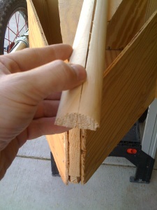
Using two quarter round mouldings to finish off the tail.

But, before we were able to sit down and get to business with the steel sheet I needed to consider the point or tail edge itself. You see where the left and right sides of the body meet in the tail, we ended up with an edge that was approximately one and a half inches wide.

Had I been more careful with the body and tail assembly I probably could have significantly reduced this to the point that all it needed was a bit of good filing and some elbow grease. But alas, I didn’t think that far ahead and here we are… with a bit of a challenge. Nothing insurmountable, just something else to keep me on my toes with this project.

I figured that I could probably use some simple wood moulding/trim to finish this off so I headed to my second home (Home Depot that is). I wasn’t able to find a single half-round that was the right size, so I settled on quarter round pieces that I figured we could just glue together.

Our custom moulding glued and held in place to dry.

I roughed up the pieces, applied a generous amount of wood glue, and held them together with rubber bands for a few hours.

After gluing the two pieces of moulding together, I then glued the entire single piece onto the back of the kart. To hold this all nice and firm against the kart I then wrapped a few lengths of painters tape around the tail which applied constant pressure to the glued surfaces.

After a few hours of drying, leaving the tape in place, I next drilled a few pilot holes through the moulding into the kart body. Since I knew I would be filing this down and generally putting some elbow grease into it, I wanted to make sure it wasn’t going to go anywhere.

Once the pilot holes were complete I set a few 2″ finishing nails through the moulding, attaching it securely to the kart. This piece wasn’t going anywhere that’s for sure.

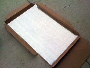
Creating a template with newspaper for our sheet metal.

Now… to think about exactly how the steel sheet would mount. I knew it would be wrapped around the shape much like we had done in the front, but I wasn’t quite sure how I would finish of the very edge where we have our moulding.

After some serious consultation with the boys (“Oh yeah sure Dad, whatever you say.”) I figured I would first put a rough layout together with newspaper.

One of the challenges we had with the front was that I didn’t use a template, but rather just measured and cut it out. I shot from the hip you might say.

In doing this I did a fair amount of trimming as we were mounting it and that was something I wanted to try to avoid here if I could. The final result there was fine, but I think in retrospect I could have made it fit better had I taken a slightly different approach. Live and learn as they say. Anyway…

Our sheet cut out just sitting in place for the moment.

With the newspaper taped in place I sketched the perimeter lines with a Sharpie to indicate the final shape that I wanted our sheet metal. I then removed the newspaper and trimmed it along the lines we just placed on it thus creating my template.

With our newspaper template now complete I placed it onto the sheet metal and once again using our Sharpie, outlined the shape. I was sure to give myself an extra half inch or so all around just to be safe.

It was about this time that one of the neighborhood kids (a girl in fact) came by and said “I wish my Dad would build me one of these.” Awesome. I must be doing something right here.

Once we outlined our template I then picked up our cheap Harbor Freight cutting shears and cut it out. The shape of our panel once mounted will follow along the seat back, along the sides following the top of the tail, and will meet at the new tail piece we put in place.

Most of our screws set revealing the final gap on the end to consider.

At the top of the tail I decided to shape the steel to match that of the half-round moulding and bend the sides around to meet it. Once it was all cut, the next step we took was to place marks at 3″ intervals around the edge of our steel and drill pilot holes through the steel. Every 3″ may seem a bit extreme, but it’s mainly to keep the steel snug against the wood.

With our pilot holes in place we next set the steel into position, with the back of it sitting nice and snug onto the seat back. Once I was happy with the side to side positioning I then set this first screw into the back center.

To try to avoid the buckling we experienced with the front, I then worked outward from this center screw along the length. After setting a couple of more screws I went ahead and set the center of the rear (this is right on the moulding we mounted) to insure the steel stayed put.

Little by little the stability and strength of our sheet increased until we had all the screws set except the final two on both sides of the rear point.

Scrap piece we'll wrap around and mount over the moulding.

I had intentionally left these loose while I considered how best to get the final bit of moulding covered. I suppose I could have done it as one complete piece but the thought of cutting segments out, with the intention that they would miraculously meet perfectly in the middle was a gamble I didn’t think I’d win. I figured working with two separate pieces just be easier to deal with.

Since we had the very top of our moulding covered (we cut a slight half circle) we only had to consider wrapping around and meeting with the already set steel on the sides. No sweat right?

I secretly borrowed my wife’s sewing measuring tape (shhhh!) and wrapped it around our moulding and measured the distance from our steel on side to the steel on the other.

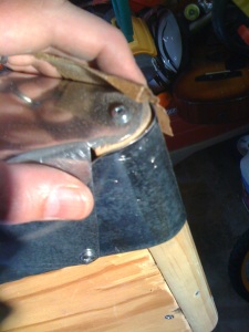
The final wrap piece in place and some sanding to remove the sharp edges.

The amount of scrap we had sitting around was perfect for a piece this small. It was easy to work with in that it was only roughly 6″ wide at the bottom and 3 1/2″ wide at the top.  I cut it out and was careful to hit with some 100 grit sand paper I had sitting around. This removed the sharp edges that were left behind when cutting it up.

Next I went ahead and drew a line down the center, so that I could align it with the center of our moulding. We will then carefully bend it around to meet up with the partially mounted sheet… well that’s the idea anyway.

I positioned our scrap onto the moulding and carefully bent it, sliding it underneath our already mounted piece.  This way we will end up with a relatively clean line of our steel and the larger piece will effectively clamp down our smaller piece nice and tight. It worked perfectly and didn’t look half bad.

As I mentioned before, so far we’ve had relatively little buckling which is great to see. The steel is bent to the curve of the wooden body and there aren’t anywhere near the bends and dents we ended up with on the front. With this final piece in place I think it will all be nice and tidy.

Once I had the sides of our scrap slid in place underneath the already mounted main piece, I then ran a screw through each side to hold it all together.

Close up revealing our installation with relatively little buckling. You can see where both pieces were screwed together near the tail.

Next with the corners screwed in, I then ran an additional screw about midway up our scrap piece, securing it firmly in place.  We now had the moulding completely covered, or wrapped around.

I discovered that in the top of the tail section, where the pieces met, a little tap here and there with a ball peen hammer did a world of good. These little taps just ever so slightly bent these raised points inward, towards the wood body making for a smoother overall finish.

After mounting this piece we still have just a hair of wood visible through the gap where the pieces meet, but it’s relatively little and isn’t really a big deal. Once we’re all painted I think it won’t be all that noticeable.

Our kart is resembling a Bugatti more and more all the time.

With this step we’ve completed all of our steel work for the body. I have some things in mind with regards to the grill but I think that will fall into place after we do some priming of the body and wood.

To prepare for priming the next step will be removing all of the exhaust, the wheels, and taping off anything with the steering components we don’t want painted.

Stay tuned, with Spring just around the corner I don’t expect our next step to be too far off.

Is it a bonnet or a hood? I suppose it may depend on which side of the Atlantic you’re from. In either case I’m speaking of the portion of the body that would cover the engine. Or in our case, the top portion of the body that will cover the riders feet and pedals.

Measuring the curvature of the dash.

This part of the body will be fashioned out of a sheet of galvanized steel. The sheet will attach over the oval top of our grill, on both sides just above the louvers, and finally to the top of our dashboard.

I thought that my local Home Depot carried some materials like this, but I wasn’t sure. Before I headed over I took all of the necessary measurements. This included the curve of the grill, the distance from the grill to the dash and the curvature of the dash as well. I jotted down my measurements, recruited a helper and then headed over. My assistant insisted we take a tour of the pre-built storage sheds in the parking lot, so after that little diversion we headed in.

The size I needed was at least 24″ long and about the same in width. It wasn’t so much that what I was going to cut was a perfect square, but rather the width was wider at the dash end than the grill end. As luck would have it I found a 24″x36″ galvanized sheet that would suit the task just fine. But how would I cut it?

Nice and new 24x36 galvanized steel sheet.

When I was a kid my dad was always welding and working with metal projects all the time. He had an industrial grade set of shears in our garage. These were seriously of the heavy grade variety and were literally bolted to the garage floor. I could sure use those now.

I can remember using those shears for the first time. I had just received my first roll-away toolbox and I wanted to line the drawers before I put my tools in. I only had extra card board to use and wasn’t sure how best to trim it.

My Dad looked at me and pointed to the shears and said “Use that… if it can cut .10 gauge steel it should have no problem with cardboard!” Sure enough he was right. Not much good it does me now but they sure were handy at the time.

The freshly cut hood mounted at each end, to the grill and the dash.

Although I have a fairly extensive collection of tools I have no shears, handheld or otherwise. I was hesitant to buy tools that I’d likely never (or at least seldom) use again so I figured I’d try out the local Harbor Freight. They’re not exactly known for professional grade quality, but they are known for inexpensive stuff.

It turned out that Harbor Freight did have some decent looking shears for $5 that I figured would be fine for cutting straight lines, which is all we need to do. Armed with our aluminum and snips I headed home to get started.

First I double and triple checked the measurements and drew out the lines on the steel. I then took our high end scissors and started cutting out our hood. I was pleasantly surprised how easy it was to cut. Not quite as easy as say paper, but in about 15 minutes I had the entire shape cut. So the cheap shears worked out just fine.

Trimming a bit extra off so that the the hood doesn't overlap with the louvers.

Once I had the shape cut I placed it onto the kart and started to determine exactly where to center it, where it would mount on the grill and where it would mount on the dash. I started by placing a center line on the newly cut hood and mounting each end at this line with a single screw. I also removed our steering wheel at this point to make mounting a bit easier.

With the piece sitting now somewhat mounted, albeit loosely, it looks like either my measurements were off or something else was amiss here. I realized that the dash wasn’t sitting perfectly vertical which caused my measurements to be slightly off. Not terribly so, but just a bit.

In addition to the length I also had a hair too much on the width. It could have been resolved by unscrewing our single screws, moving it over slightly, and resetting it. Since I had already drilled a number of pilot holes, and the steel was easy to trim, I went ahead and cut a bit off rather than try to reposition the whole thing.

Curving around the dashboard and setting the screw.

Now that the fit is a bit more accurate I started to set the remaining screws, working my all the way around. Once the curve was set I was surprised how much strength the entire hood had. I mean you could still dent it with a fist, but it still was quite sturdy.

As I worked around the perimeter, drilling pilot holes, then running the screws the edges started to slightly buckle. It’s not quite like say smoothing a piece of linen… it really didn’t want to lie flat.

I worked my way from the grill towards the dash, tightening and slightly buckling, my way along the edge of the steel. Once I reached the dash I had to push down to hold it as flat as possible to keep the curve nice and tight.

If I had to guess I’d say that when race cars of this vintage were brand new, automotive technology being what it was in the 1920s, I’d guess that these came “brand new” with their share of dings and dents so I’ll just chalk this buckling up to realism. Yeah, that’s it….realism.

I think resetting some of the screws will resolve some of the buckling.

I finally set all the remaining screws in place. As I fastened them I also hit the edge of the steel sheeting with some sand paper. This stuff can really have a razor edge to it, especially places where I have cut it.

It’s nice to see what previously looked like a go kart missing some critical pieces, is now starting to really resemble a vintage race car.

Aside from the trip to Home Depot I didn’t have the assistance I’ve had with the earlier steps, the boys were busy riding their bikes up and down the street.

Birds eye view of our hood. Starting to look similar to our overhead Bugatti shot in Chapter 6.

The boys took a break from dragging everything they own down the street and came up to the garage. They glanced my way and commented how good it looked. They really looked thrilled to see this in place, so I must be doing something right. I do have to admit that immediately after the comment they asked for something to eat. I’d like to think they came up to check on my progress and the request for food was simply an afterthought.

With it all now set in place I pulled the car out to see where we stood and get some pictures. The car and the hood will all be painted so after a bit of playing around I think it will all look fine.

The overhead view also shows the hood as it meets the dash. This will give us plenty of opportunity to mount a frame for a windscreen later. The view from the riders perspective isn’t so bad either.

Our next step will be applying a sheet of steel to the rear deck (boot? trunk?) and going through similar steps we have here.

This next step in our project involves the hands of a surgeon and nerves of steel. OK, it’s not quite that bad, but was rather nerve racking. You see at this point I needed to carefully bend the rear panels towards one another, and screw them together. Doing this will create the very vintage boat tail rear look to our kart, plus it will just look cool.

Just what exactly is this boat tail design anyway? It’s all the rage, all the cool kids are doing it! This body design in automotive carriage building has been around for quite some time, beginning in the early 20th century. The main attraction was for aerodynamics, making the car generally more sleek and faster. Of course the end result also was that the rear of the car ends up having a general shape that resembled that of an old boat.

A great overhead shot of a 1925 Bugatti Type 35

A great overhead shot of a 1924 Bugatti Type 35

Some great examples in this time period include the 1933 Duesenberg, the 1936 Auburn Boat Tail Speedster, the 1934 Packard 12 Boat Tail Speedster and of course the Bugatti Type 35 that we’re loosely basing our project on.

There were also more recent (and questionable) examples including the 1971 Buick Riviera. Nothing however could replace the original art deco era cars, they really are just priceless.

On our project we had the body mounted on both sides with the rear waiting for the final assembly. In order to secure the rear panels to one another in the back I needed to first create the boat tail “base” that both sides will attach to.

This base is a triangle that mounts to the rear of the frame, and the body panels are bent inward to attach to the triangle itself. I set a line down the center of both the rear cross member, as well as the tail brace, drilled pilot holes through the rear cross member, into the brace and followed up with 1 1/4″ wood screws.

Boat tail support base that both panels mount to.

Boat tail support base that both panels mount to.

After I mounted the boat tail brace to the frame, I then had to cut what amounted to a long triangle block that mounts vertically at the absolute rearmost point in this boat tail.

This vertical brace effectively acts as the edge of the tail, and adds some strength and rigidness to the whole structure. Cutting this piece was a bit of a challenge, since as before, I still didn’t have my table saw. Again creative cutting with the Skil saw would be in order.

I basically needed to cut a 9″ deep triangle out of a 2×4. It took me a few tries to get the angle correct, but I finally got it right. Once I cut this piece out completely I mounted it vertically onto the rear point of the tail base.

Cutting this piece to be used vertically in the boat tail was a bit of a challenge.

Cutting this piece to be used vertically in the boat tail was a bit of a challenge.

Next I very carefully bent the left panel against the triangle brace, drilled pilot holes through the panel into the brace, and followed up with 1″ wood screws. As I bent it over and set the screws I heard the very distinct sound of wood slightly cracking. Eeek. The plywood, very slightly, began to crack right where our kerf lines were cut. Nothing too significant, just a very slight hint. I think I can file it down and fill it with wood putty and you’ll never know. Well, I’ll know but I’ll never tell.

After attaching the left panel, I carefully bent the right panel over and did the same, drilling pilot holes and inserting soaped up wood screws.

The meeting of both panels to the rear against this vertical board will need some smoothing over and likely some filler as well, but the end result is quite sturdy.

After mounting things up I realized that the vertical brace actually extends about 1.5″ higher than the body panels. Hmm. I wasn’t quite sure why but I did confirm it was the correct size based on the plans. On closer look there is another piece that will be mounted on top of the boat tail at a later point, so I think we’re all good here.

Both panels attached to rear vertical beam and boat tail bottom.

Both panels attached to rear vertical beam and boat tail bottom.

After assembling the tail I realized it is probably strong enough, and has enough space, to house a small engine or electric motor in the future. I could easily see a small gas engine, or even some of the small electric motors readily available for the various Razor products fitting right in here. The vicinity of a motor here to the rear wheel sprocket would be pretty easy to work with as well. The boys are a bit too young, and my wife won’t even let me consider it, so I’ll leave this for another day. Though maybe if I sprang for a weekend getaway for her, she’d never notice if I dropped one in while she was gone?? Couldn’t take more than an afternoon right??

Since I was making some great progress, and it had been a whole 15 minutes since someone asked me if I was done yet, I figured I’d keep going while I had the opportunity.

Next I’ll add the seat. In preparation of this I mounted the cleats, or mounting braces, on the inside of the body panels. I mounted these a half inch lower on the body to account for my older son. I wanted the boys to be able to fit into this as long as possible, so where I could I tried to account for dimensions with that in mind. I also placed them a bit further back from the original mounting spots since I’ll be adding a crank with pedals.

Next I cut out the base of the seat and the seat back. The base has a slightly narrowed shape to account for the portion of the tail where the bend begins. The seat back will be mounted vertically and has braces attached to the top, left and right sides. The plans call for a brace on the bottom as well. I opted not to use a bottom mount since I felt it a bit redundant, not to mention risky with regards to running the screws into it. When cutting the seat back I followed the plan in making it rounded on the top, but opted to make it a bit taller than the plans called for. Again, accounting for longevity of use (or at least hoping to).

Seat base and back mounted into the body.

Seat base and back mounted into the body.

I placed the seat bottom onto the seat braces. I then drilled guide holes through the bottom and into the seat braces I previously mounted to the body panels. At this point we actually had something to sit in and it was getting pretty exciting.

Right about now I was wishing I was 6 or 7 years old. Then again if I were I wouldn’t be using a Skil saw and my Dad would be putting this off to another time, so never mind.

Once the seat bottom was mounted I slid the vertical seat back into place. This was a tight fit, which is good. I wanted to get it as close as I could to the panels, but also didn’t want to force the panels outward. Once this seat back was in place I then drilled guide holes and ran wood screws into the side braces of the seat back from the OUTSIDE of the body panels. This was one of the cases where at a later point prior to painting I’ll fill these screws and with any luck they won’t be visible in the least.

The seat back braces are clearly visible in this shot. The upper brace will be used for mounting another piece later.

The seat back braces are clearly visible in this shot. The upper brace will be used for mounting another piece later.

We now have the tail and seat in place. Next up will be getting the dashboard and steering mechanism cut and put in. All in all a very productive day for sure.

The neighbors are beginning to ask questions so that should be a good sign right? Only I wish they weren’t asking “What is that?”.